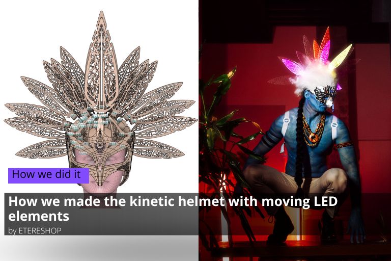
Today, we will talk about one of our latest developments – the kinetic helmet. We will tell you how we made the kinetic helmet with moving elements and the difficulties we faced.
Contents
Inspiration
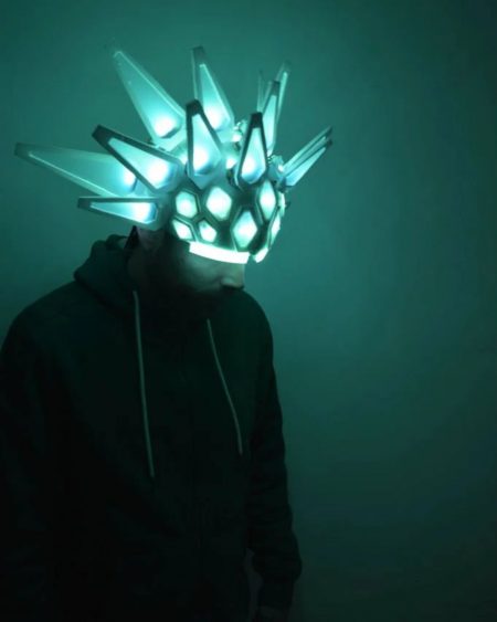
The idea for creating this helmet started with the marketing department’s idea to create something interesting, where some parts of the product moved and seemed alive. They analyzed products on the market and found a couple of very old but quite impressive helmet and dress projects with opening elements. Inspired by these ideas, the marketing department came to the development department with questions about implementing a similar project. After a small brainstorming session and sketching out the idea, it was decided to make a helmet with glowing feathers that would move similar to the hedgehog helmet shown in Figure.
The idea of a kinetic LED helmet with moving elements viewed from the side.
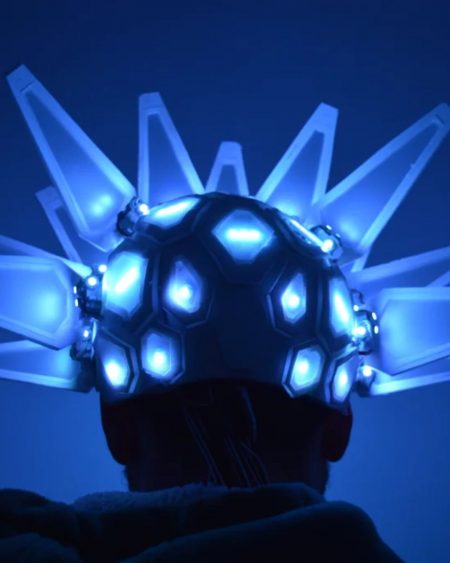
The idea of a kinetic LED helmet viewed from the back
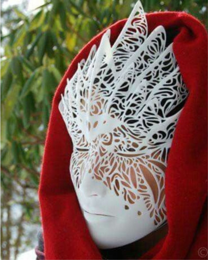
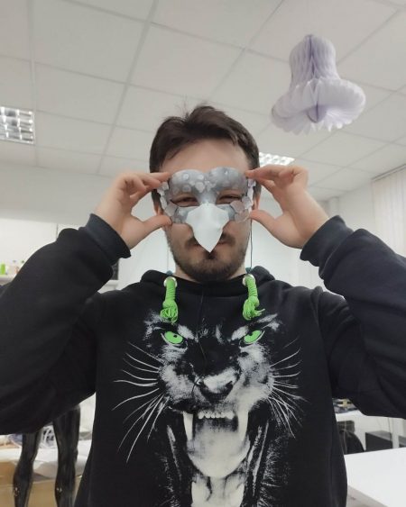
An example of a face mask. To visually enhance the kinetic helmet, we decided to add a face mask.
The development of this was taken up by Anatoly.
Developer Anatoly
Implemented projects of the developer Anatoly
Anatoly is a leading specialist in the field of software development, as well as integration of new technologies and control controllers.
In 2017, he integrated new controllers based on the ESP8266 microcontroller and until 2019, he was engaged in supporting firmware for controllers based on them.
In 2016, he came up with and recreated the logic of recorded effects, which is still used in all firmware versions.
Throughout 2018, he worked on writing an ArtNet recorder for the Windows operating system to record effects from programs that can transmit effects using this protocol.
In 2019, he wrote a screen recorder for capturing images from the monitor screen, which expanded the possibilities for clients and allowed clients using MacOS not to be left behind.
From late 2019 to 2020, he wrote the first firmware that allowed converting data received via the DMX protocol and transmitting it using radio. Also, at the end of 2019, Anatoly got acquainted with the Touchdesigner development environment and made the first project based on it – a dress with UHD boards and Raspberry Pi as the control controller.
Inspired by the capabilities of this environment, in 2020 Anatoly created a sandbox that used Kinect to determine the height and complexity of the relief and illuminated areas with different colors based on height using a projector.
One of the most complex and long-term projects was the projection dance 3D cube, which involved interaction between the participant and the effects on the stage.
In early 2022, Anatoly developed unique control for large dodecahedrons and tubes, allowing them to be controlled using a MIDI console through Touchdesigner. Read more in the article.
Software development
During the idea discussion stage, it was unanimously decided to use servo motors to control the feathers. The first task was to choose a controller and write a test firmware. Several types of microcontrollers were considered:
STM32,
ESP8266,
ESP32,
Arduino,
Teency.
The first test firmware worked by receiving data via the DMX protocol, processing it with the controller, and thereby controlling the servo motors. However, the Teency microcontroller was immediately ruled out due to its high cost, and the STM32 was also rejected because it lacked working libraries for receiving DMX data.
The ESP8266 also did not meet expectations due to the lack of open-source libraries for receiving DMX data, as well as the small number of free pins for servo motors. The Arduino microcontroller showed good results but had to be abandoned because it could only control eight servo motors.
Therefore, the ESP32 microcontroller was chosen, and the first tests showed good results, allowing the control of 16 servo motors simultaneously. The next step was to expand the firmware logic to control both motors and LEDs simultaneously, which encountered some difficulties.
Firstly, they had to abandon the DMX protocol due to problems with LED control. This setback sent the whole project back to the beginning. The next attempt was to use the I2C bus, but it also failed due to library issues. Eventually, the solution was to use Serial, which allowed the firmware to control both the motors and LEDs using the same effect.
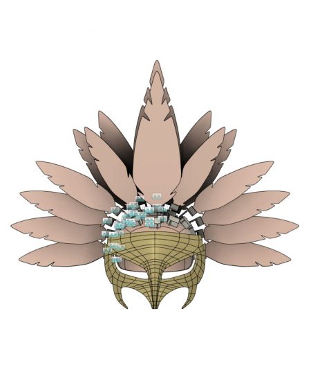
Designing a Helmet Model
The next stage of development was the construction of a 3D model of the helmet. All work was done in Fusion 360. This program allows you to work out all the details, attachments, and shapes, as well as simulate the movement of the necessary parts. After several days of work, the first helmet model was created.
The first model of kinetic LED helmet
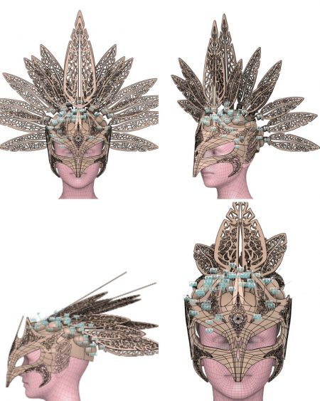
This model already looked quite interesting and practical, but it appeared too simple and plain. Therefore, it was decided to add some decorative elements to make the helmet more appealing: make the feathers more textured, add patterns to the mask, and also make it slightly taller to hide the servo drives in the enclosures. As a result, the helmet acquired the following appearance.
Second helmet model by ETEREshop
Now the helmet looked more elegant and interesting, and based on this model, details were further developed.
Development of parts for a kinetic LED helmet
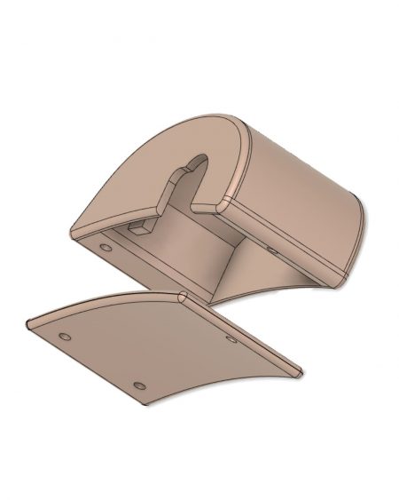
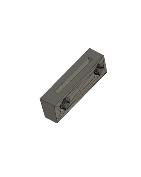
The first thing that needed to be done was to create housings for the servo motors. In order to be able to service the motors if necessary, a detachable motor housing was developed that will be 3D printed and attached to the head.
Model of the servomotor housing.
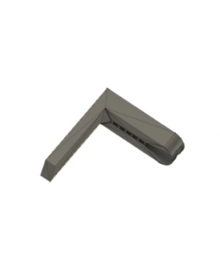
The next task was to come up with a way to attach the feathers to the motor. The first model looked like this:
Feather attachment to motor
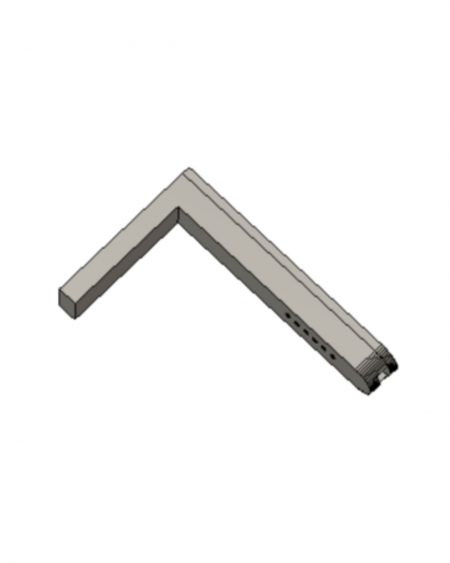
However, after printing a test sample, it turned out that this attachment was too short and severely restricted the movement of the feather. Therefore, the model was redesigned and took the following form:
Final feather attachment
A tape is mounted in the upper part of the lever, so for ease of installation, the part was divided into 2 parts, the lever itself and part of the pen attachment.
Feather attachment part
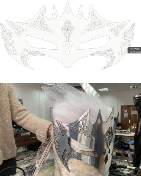
Next, we needed to work on the mask. Initially, it was planned to 3D print this mask. However, due to the complexity of the shape and the large number of elements, the cost of printing was quite high. Therefore, it was decided to redesign the mask and replace the material with Italian mirror plastic.
New design of the mask
Preparing materials
After the model was completed, it was time to prepare the materials for assembling the helmet.
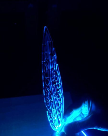
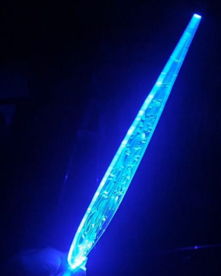
Firstly, it was necessary to choose the material for the feathers and check if they wouldn’t be too heavy. It was also necessary to check how well they light up. The material chosen was 2mm plexiglass. It turned out to be quite lightweight, but the full perforation of the feather did not work very well when attempting to light up the end.
Pen illumination with perforation
Feather lighting with perforation
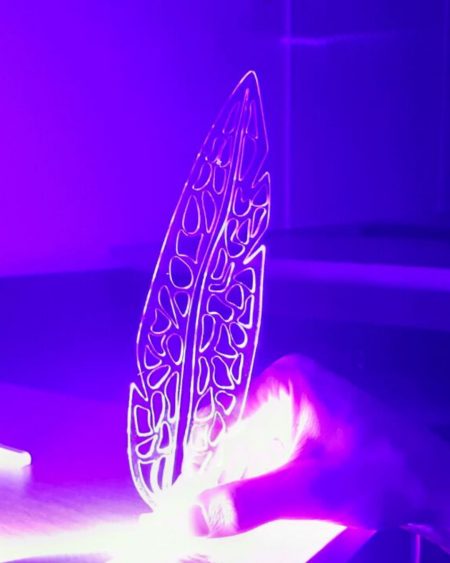
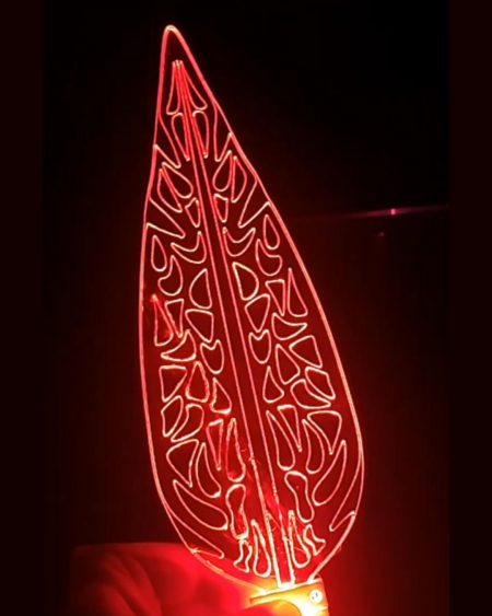
Due to the large number of holes, the light refracts very strongly and does not reach the top of the feather. For this reason, it was decided to replace perforation with engraving. Engraving worked much better.
Feather lighting with engraving-1
Feather lighting with engraving-2
Next, we had to choose the material for the helmet liner and figure out the issue of wire placement. We decided to use the model of a standard helmet liner from another helmet but make it with 2 layers: the upper layer is 2mm EVA, and the lower layer is 5mm EVA. This construction allows the helmet to be disassembled and hide the wires between the layers.
Upper layer of the cap
However, after assembling the entire helmet and conducting tests, the decision was made to use 5mm EVA for both layers in the future.
Helmet assembly
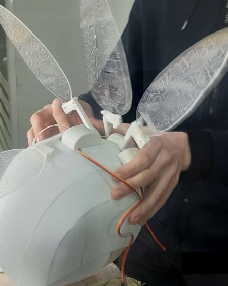
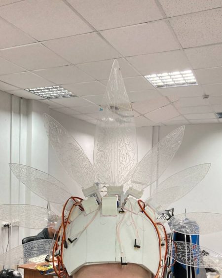
And so the long-awaited moment of assembling the helmet had arrived. The first task was to glue the EVA foam caps together, but that was the easiest task of all. The next step was to mark the caps to place the servo motors. The task was slightly more challenging than it seemed at first glance. The difficulty was in ensuring that the helmet was symmetrical in all feather positions, so every millimeter played its role. After some time, this task was solved, but for future reference, it was decided to add engraving on the EVA foam for positioning. Also, during the placement of the servo motors, it was necessary to abandon several feathers because they interfered with each other’s operation, and the total number was reduced to 12.
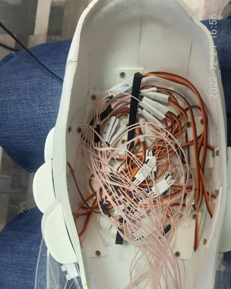
And with that, the easy part of the work was finished. The next step was the long and meticulous work with electronics. They started with the basics, attaching tape to each lever for the feather. Channels were pre-worked in it to hide the wires that connect to the tape, but due to the small size of the part itself and a very small strip of tape, this work took a decent amount of time. Also, it’s worth noting that the tape requires three wires to operate, and on the entire helmet, there are 36 wires for the LED tape alone. Add the same number for the servo motors, and in the scale of such a small helmet, it’s a whole heap of wires that need to be hidden and neatly laid out.
Adding wires to the helmet
But more on that later. The first thing they needed to do was to place everything on the helmet and lead these wires to its internal part. As mentioned earlier, the servo motor housings were made to be disassembled, and one of the reasons was ease of installation. The main part where the motor is hidden is located at the top of the cap, and the cover that should close this box is on the inside of the helmet, creating a convenient serviceable structure without any excess glue.
Motor mount
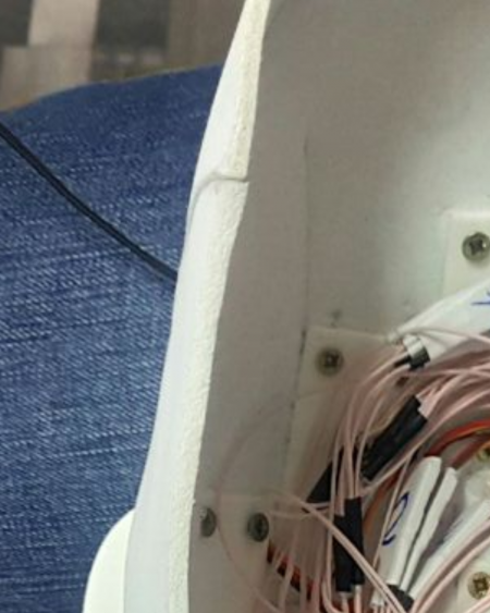
They repeated this procedure 12 times, and now all the motors are in place. Then they made several neat holes with a needle in the EVA foam and passed the wires down. And now, back to that daunting picture of a heap of wires.
Wires in the helmet
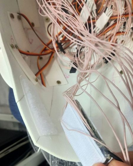
To ensure proper operation and correct distribution of power, all of these wires needed to be connected to a common wire. As a result, we have 74 wires that need to be neatly laid inside the helmet. The task is not easy, but entirely feasible. Using cable ties and hot glue, all of these wires turned into neat strips that are laid out all over the helmet. And let’s not forget that we still need a controller, or to be precise, two controllers that interact with each other.
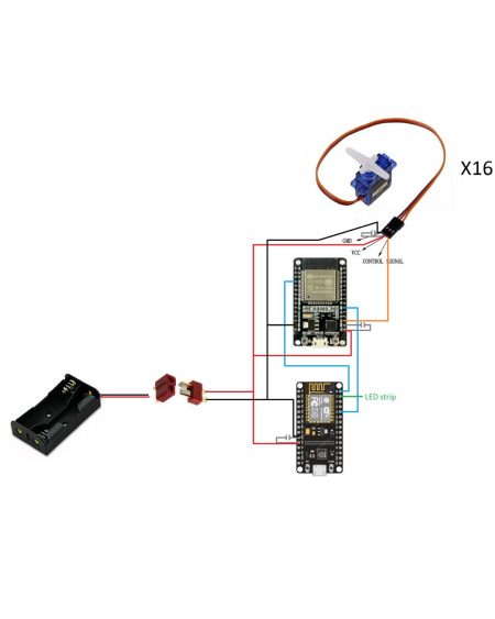
General diagram of the controller
The only thing left is to secure the feathers and the mask. Attaching the feathers is not a difficult task, so we managed to do it fairly quickly. The process is simple – insert the feather into the fastener, secure it, and glue the fastener onto the lever.
Mounting the pen
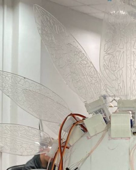
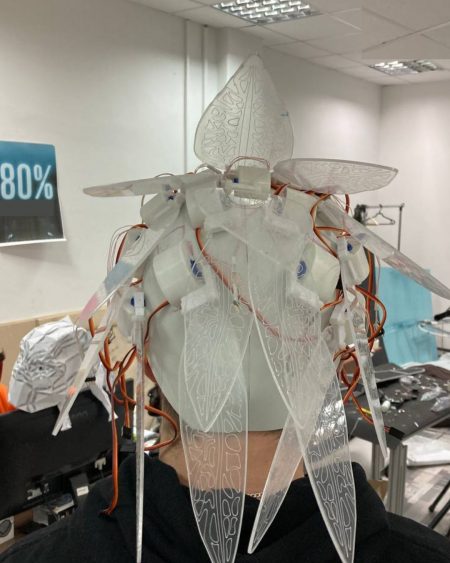
And after several hours of work, we finally had the first outlines of the coveted helmet.
First outlines of the helmet
Kinetic helmet, rear view
We’re on the home stretch, attaching the mask.
We fasten the mask
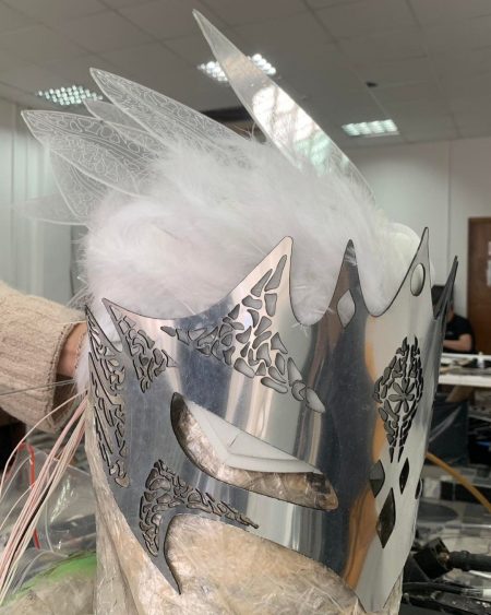
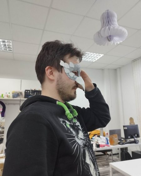
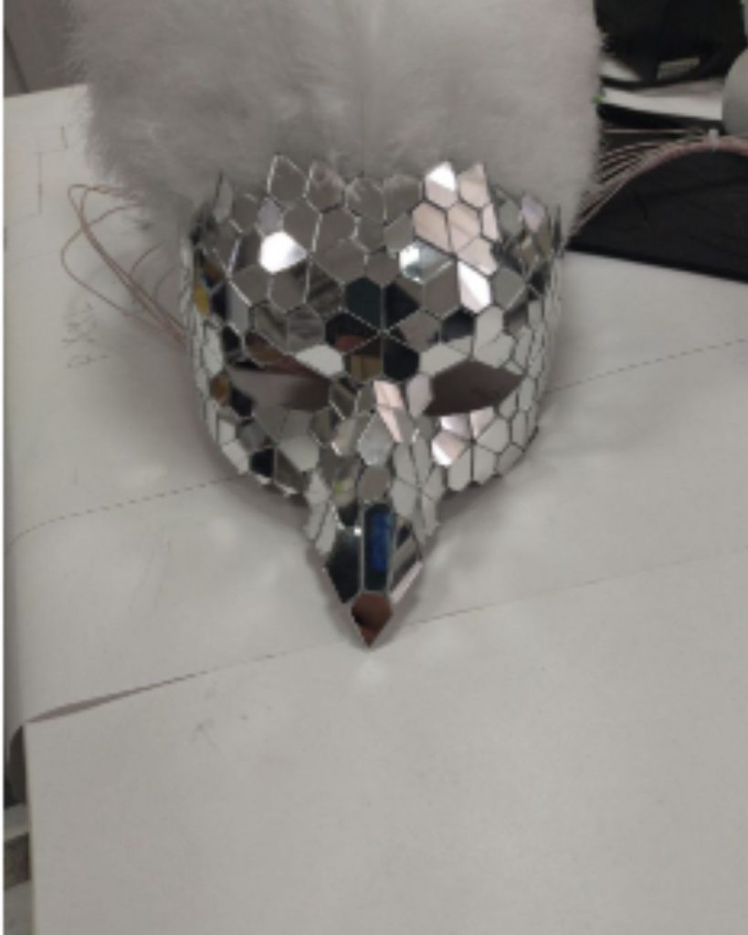
And we realized that the mask looked too large compared to the rest of the helmet and was not very practical. But a solution to the problem was quickly found – we simply took a regular masquerade mask, adjusted its shape a bit, covered it with mirrors, and voila, a new mask was ready.
New mask shape, front view
New mask shape, side view
Ready-made mask
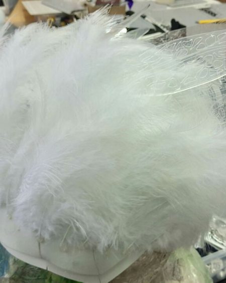
Since the shape of the mask is now different and the motor housings do not cover anything, we decided to add some artificial feathers to cover everything up.
A helmet decorated with feathers.
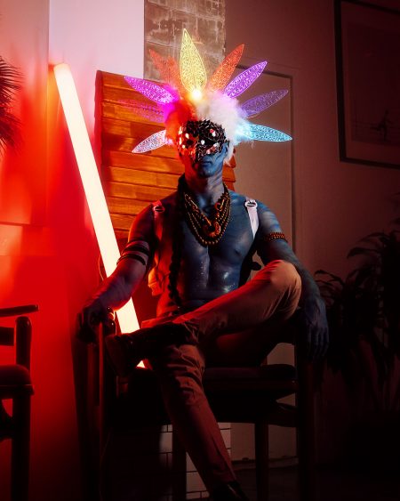
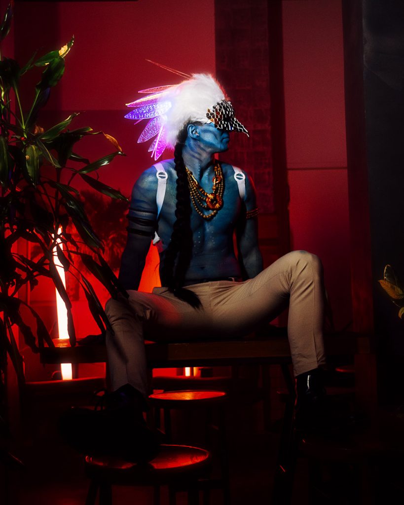
A few tweaks to the code and effects settings, and everything is ready. The kinetic mask in our execution.
A colossal amount of work was done using new technologies and approaches. This experience will allow us to expand the range of products and create something even more grandiose and impressive. Of course, it was not without problems and mistakes, but all the nuances and shortcomings have been taken into account, and in future projects, everything will find new life.
If you liked the article or you found something useful, share the article with your friends, we will be pleased.